串口控制led闪烁可调频率
项目gitlab地址: http://120.55.75.228:23080/zhdyz/axi_lite_led
任务需求
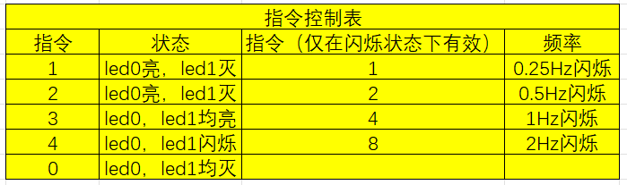
电脑端串口调试助手发送指令到PS端串口,PS端根据指令控制PL端LED灯的状态
PL端led灯分别为led0,led1,状态与控制指令如下所示,可通过指令调整频率
实验流程
IP核创建
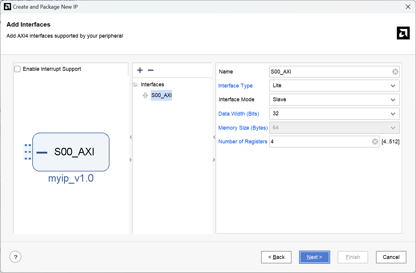
创建一个如下类型的IP核,类型为AXI_Lite,模式为Slave,使用4个寄存器(最少4个)
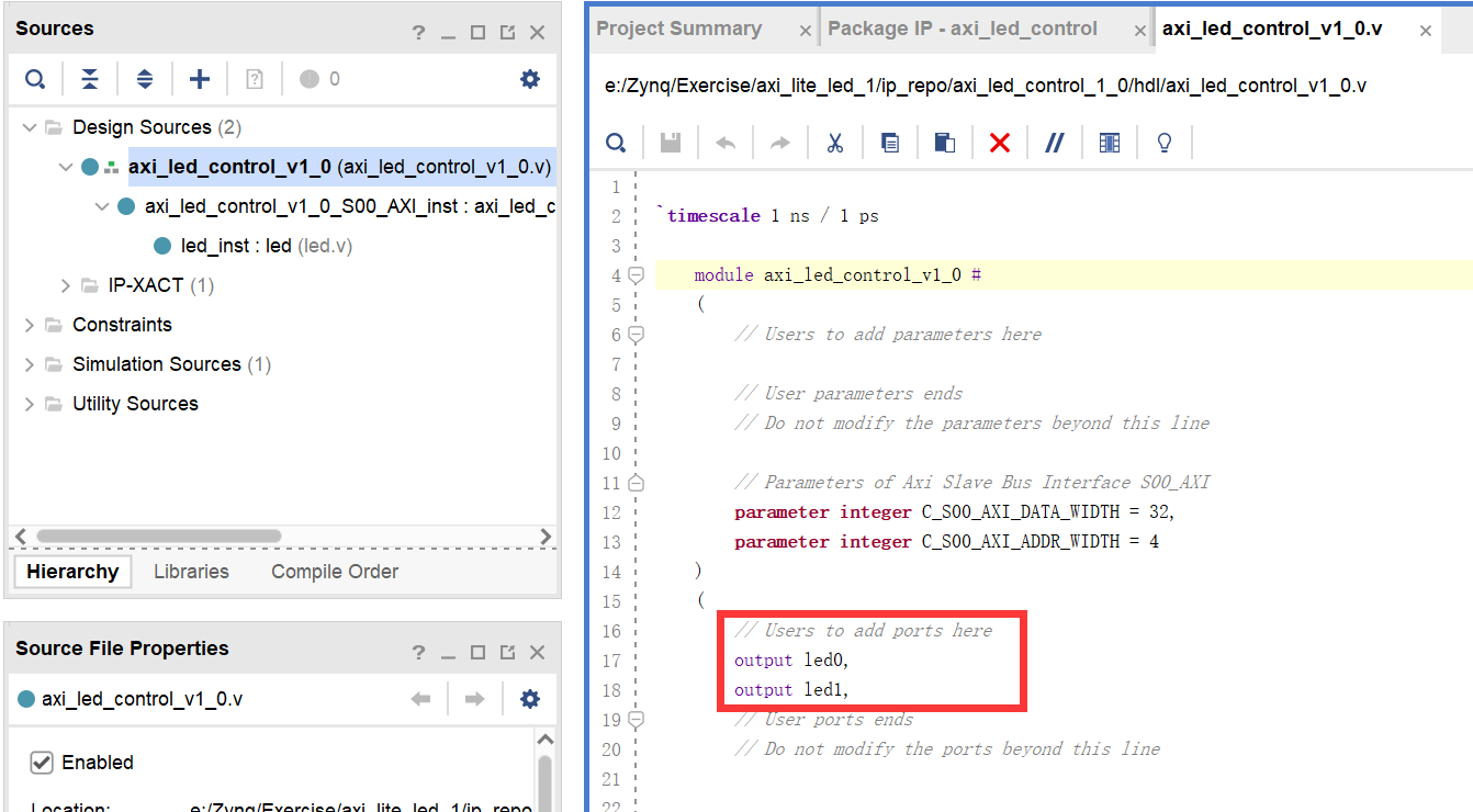
然后编辑代码,因为要控制PL端的led0,led1,所以添加端口
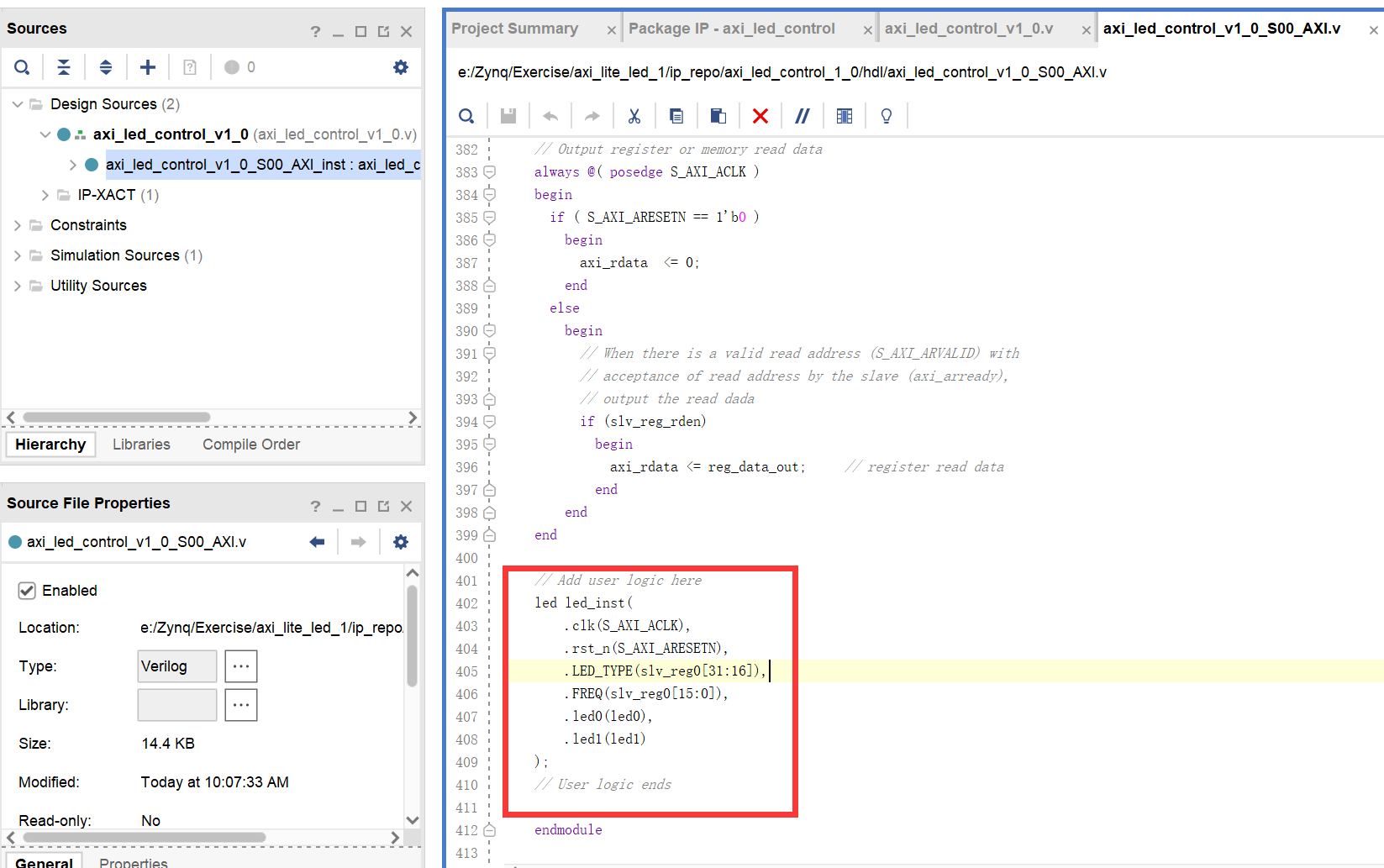
添加模块led.v,功能为根据LED_TYPE和FREQ控制led的亮灭和闪烁
`timescale 1ns / 1ps


module led(
    input clk,
    input rst_n,
    input [15:0] LED_TYPE,
    input [15:0] FREQ,
    output reg led0,
    output reg led1
    );
//测试用
//wire [15:0] LED_TYPE1;
//assign LED_TYPE1=1;

reg clk1,clk2,clk3,clk4;
reg [31:0]cnt4;
//clk4 = 2HZ
always@(posedge clk or negedge rst_n) begin
    if(!rst_n) begin
        clk4<=0;
        cnt4<=0;
    end
    else begin
        if(cnt4==12499999) begin
            cnt4<=0;
            clk4<=~clk4;
        end
        else cnt4<=cnt4+1;
    end
end
//clk3 = 1HZ
always@(posedge clk4 or negedge rst_n) begin
    if(!rst_n)
        clk3<=0;
    else
        clk3<=~clk3;
end
//clk2 = 0.5HZ
always@(posedge clk3 or negedge rst_n) begin
    if(!rst_n)
        clk2<=0;
    else
        clk2<=~clk2;
end
//clk1 = 0.25HZ
always@(posedge clk2 or negedge rst_n) begin
    if(!rst_n)
        clk1<=0;
    else
        clk1<=~clk1;
end
always@(posedge clk or negedge rst_n) begin
    if(!rst_n) begin
        led0<=1;
        led1<=1;
    end
    else begin
        if(LED_TYPE==0) begin
            led0<=0;
            led1<=0;
        end
        else if(LED_TYPE==1) begin
            led0<=1;
            led1<=0;
        end
        else if(LED_TYPE==2) begin
            led0<=0;
            led1<=1;
        end
        else if(LED_TYPE==3) begin
            led0<=1;
            led1<=1;
        end
        else if(LED_TYPE==4) begin
            if(FREQ==1) begin
                if(clk1==1) begin
                    led0<=1;
                    led1<=1;
                end
                else begin
                    led0<=0;
                    led1<=0;
                end
            end
            else if(FREQ==2) begin
                if(clk2==1) begin
                    led0<=1;
                    led1<=1;
                end
                else begin
                    led0<=0;
                    led1<=0;
                end
            end
            else if(FREQ==4) begin
                 if(clk3==1) begin
                    led0<=1;
                    led1<=1;
                end
                else begin
                    led0<=0;
                    led1<=0;
                end
            end
            else if(FREQ==8) begin
                if(clk4==1) begin
                    led0<=1;
                    led1<=1;
                end
                else begin
                    led0<=0;
                    led1<=0;
                end
            end
        end
        else begin
            led0<=led0;
            led1<=led1;
        end
    end
end
然后在AXI IP核内实例化这个模块,4个寄存器中只使用了寄存器0(slv_reg0),其中LED_TYPE为寄存器0的31-16位,FREQ为寄存器0的15-0位,即PS端向寄存器0写入值相当于对LED_TYPE和FREQ两个参数赋值
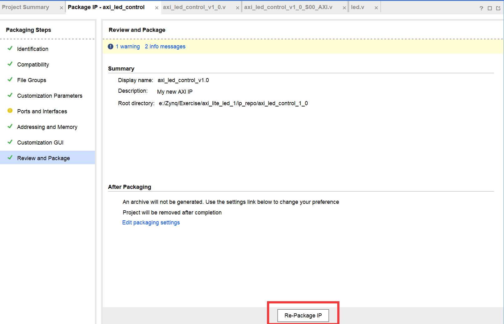
AXI IP核设计好后进行封装
然后在目录中找到Makefile进行替换,具体看文章 头文件xparameters.h无法找到
同时IP核封装好后会自动生成axi_led_control.h头文件供后面Vitis编程使用,内容如下
#ifndef AXI_LED_CONTROL_H
#define AXI_LED_CONTROL_H


/****************** Include Files ********************/
#include "xil_types.h"
#include "xstatus.h"

#define AXI_LED_CONTROL_S00_AXI_SLV_REG0_OFFSET 0
#define AXI_LED_CONTROL_S00_AXI_SLV_REG1_OFFSET 4
#define AXI_LED_CONTROL_S00_AXI_SLV_REG2_OFFSET 8
#define AXI_LED_CONTROL_S00_AXI_SLV_REG3_OFFSET 12


/**************************** Type Definitions *****************************/
/**
 *
 * Write a value to a AXI_LED_CONTROL register. A 32 bit write is performed.
 * If the component is implemented in a smaller width, only the least
 * significant data is written.
 *
 * @param   BaseAddress is the base address of the AXI_LED_CONTROLdevice.
 * @param   RegOffset is the register offset from the base to write to.
 * @param   Data is the data written to the register.
 *
 * @return  None.
 *
 * @note
 * C-style signature:
 * 	void AXI_LED_CONTROL_mWriteReg(u32 BaseAddress, unsigned RegOffset, u32 Data)
 *
 */
#define AXI_LED_CONTROL_mWriteReg(BaseAddress, RegOffset, Data) \
  	Xil_Out32((BaseAddress) + (RegOffset), (u32)(Data))

/**
 *
 * Read a value from a AXI_LED_CONTROL register. A 32 bit read is performed.
 * If the component is implemented in a smaller width, only the least
 * significant data is read from the register. The most significant data
 * will be read as 0.
 *
 * @param   BaseAddress is the base address of the AXI_LED_CONTROL device.
 * @param   RegOffset is the register offset from the base to write to.
 *
 * @return  Data is the data from the register.
 *
 * @note
 * C-style signature:
 * 	u32 AXI_LED_CONTROL_mReadReg(u32 BaseAddress, unsigned RegOffset)
 *
 */
#define AXI_LED_CONTROL_mReadReg(BaseAddress, RegOffset) \
    Xil_In32((BaseAddress) + (RegOffset))

/************************** Function Prototypes ****************************/
/**
 *
 * Run a self-test on the driver/device. Note this may be a destructive test if
 * resets of the device are performed.
 *
 * If the hardware system is not built correctly, this function may never
 * return to the caller.
 *
 * @param   baseaddr_p is the base address of the AXI_LED_CONTROL instance to be worked on.
 *
 * @return
 *
 *    - XST_SUCCESS   if all self-test code passed
 *    - XST_FAILURE   if any self-test code failed
 *
 * @note    Caching must be turned off for this function to work.
 * @note    Self test may fail if data memory and device are not on the same bus.
 *
 */
XStatus AXI_LED_CONTROL_Reg_SelfTest(void * baseaddr_p);

#endif // AXI_LED_CONTROL_H
Block Design
创建新项目,打开Block Design,创建Zynq IP核,配置好ddr型号和启用UART,其他保持默认
然后添加刚才创建的IP核,连线,如下图所示
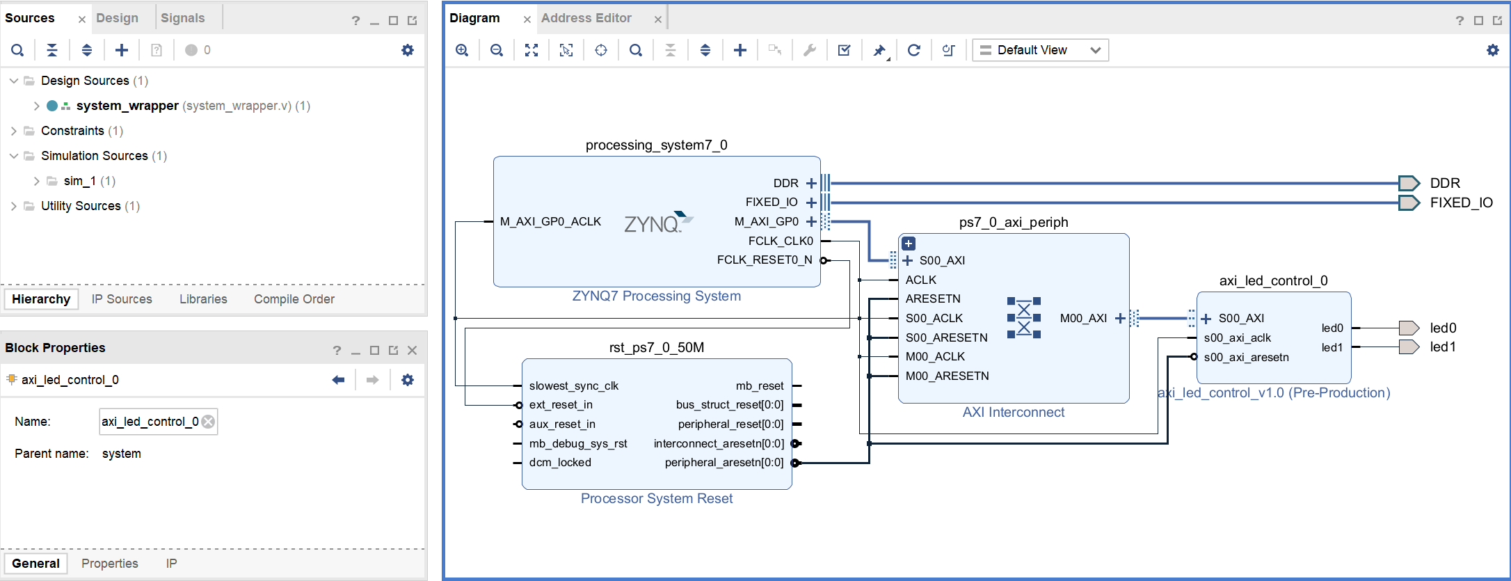
封装Block Design,将led0,led1分配管脚,生成bitstream,然后导出xsa
Vitis设计
导入xsa,新建main.c,内容如下,实现了PS端串口收发指令来向寄存器写入参数
#include "stdio.h"
#include "xparameters.h"
#include "xil_printf.h"
#include "axi_led_control.h"
#include "xil_io.h"
#include "sleep.h"

#define  LED_IP_BASEADDR   XPAR_AXI_LED_CONTROL_0_S00_AXI_BASEADDR  //LED IP基地址
#define  LED_IP_REG0       AXI_LED_CONTROL_S00_AXI_SLV_REG0_OFFSET  //LED IP寄存器地址0

//main函数
int main()
{
 //范围为0,1,2,3,4,其余无效
 int led_type=3;
 //范围为1,2,4,8,其余无效
 int freq=1;
 //32位指令
 int instruction;
 xil_printf("LED User IP Test!\r\n");
 while(1){
	 xil_printf("input a number to control led\r\n");
	 scanf("%d",&led_type);
	 if(led_type==1||led_type==2||led_type==3){
		 instruction=(led_type<<16)+freq;
		 AXI_LED_CONTROL_mWriteReg(LED_IP_BASEADDR,LED_IP_REG0,instruction);//调用API向寄存器写入值
	 }
	 else if(led_type==4){
		 xil_printf("input a number to control freqence\r\n");
		 scanf("%d",&freq);
		 instruction=(led_type<<16)+freq;
		 AXI_LED_CONTROL_mWriteReg(LED_IP_BASEADDR,LED_IP_REG0,instruction);//调用API向寄存器写入值
	 }
   }
}
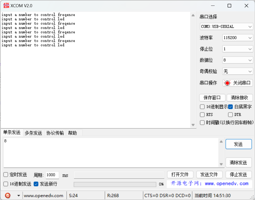
测试结果
串口调试助手输入数字指令
0.5Hz闪烁
1Hz闪烁
2Hz闪烁
本文章使用limfx的vscode插件快速发布