dma将PL数据搬运到PS内存
gitlab项目地址:http://120.55.75.228:23080/zhdyz/ad_dma_ddr
任务需求
使用DMA将PL端不断产生的数据搬运到PS的ddr中,然后PS端读取内存数据通过串口打印测试是否正确
理论分析
在 ZYNQ SOC 开发过程中,PL 和 PS 之间经常需要做数据交互。
- 对于传输速度要求较高、数据量大、地址连续的场合,通过 AXI DMA 来完成。
- 而对于数据量较少、地址不连续、长度不规则的情况,以通过BRAM来进行数据的交互
本次实验根据需求采用DMA方式实现数据交互
DMA
DMA(Direct Memory Access,直接存储器访问)是计算机科学中的一种内存访问技术。它允许某些计算机内部的硬件子系统(外设)独立地直接读写系统内存,而不需要中央处理器(CPU)介入处理。
如果不用DMA搬运数据,那么中央处理器就需要从来源把每一片段的数据复制到寄存器中,这一过程一直占用CPU的资源。
当使用DMA时,CPU向DMA控制器发出一个存储传输请求,当DMA控制器接收到请求就会将数据从源地址搬运到目的地址。在数据搬运过程中不占用CPU资源,CPU可以执行其它操作,当传输完成时DMA以中断的方式通知CPU。
进行一次传输,DMA 控制器必须得到以下数据:
- 源地址 - 数据读出的地址
- 目的地址 - 数据写入的地址
- 传输长度 - 被传输的字节数
Zynq开发中 可以在 PL端 中使用的软核 AXI DMA IP,利用 AXI_HP 接口完成高速的PL端与PS端DDR间的数据传输
根据下表,使用PL端的DMA软核 + AXI_HP接口可以达到近1200MB/s的吞吐率
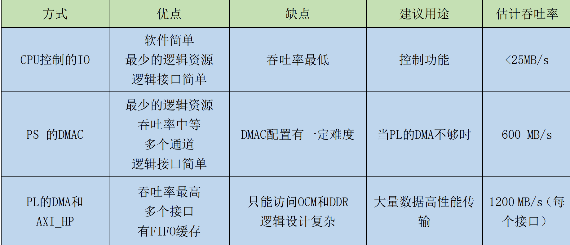
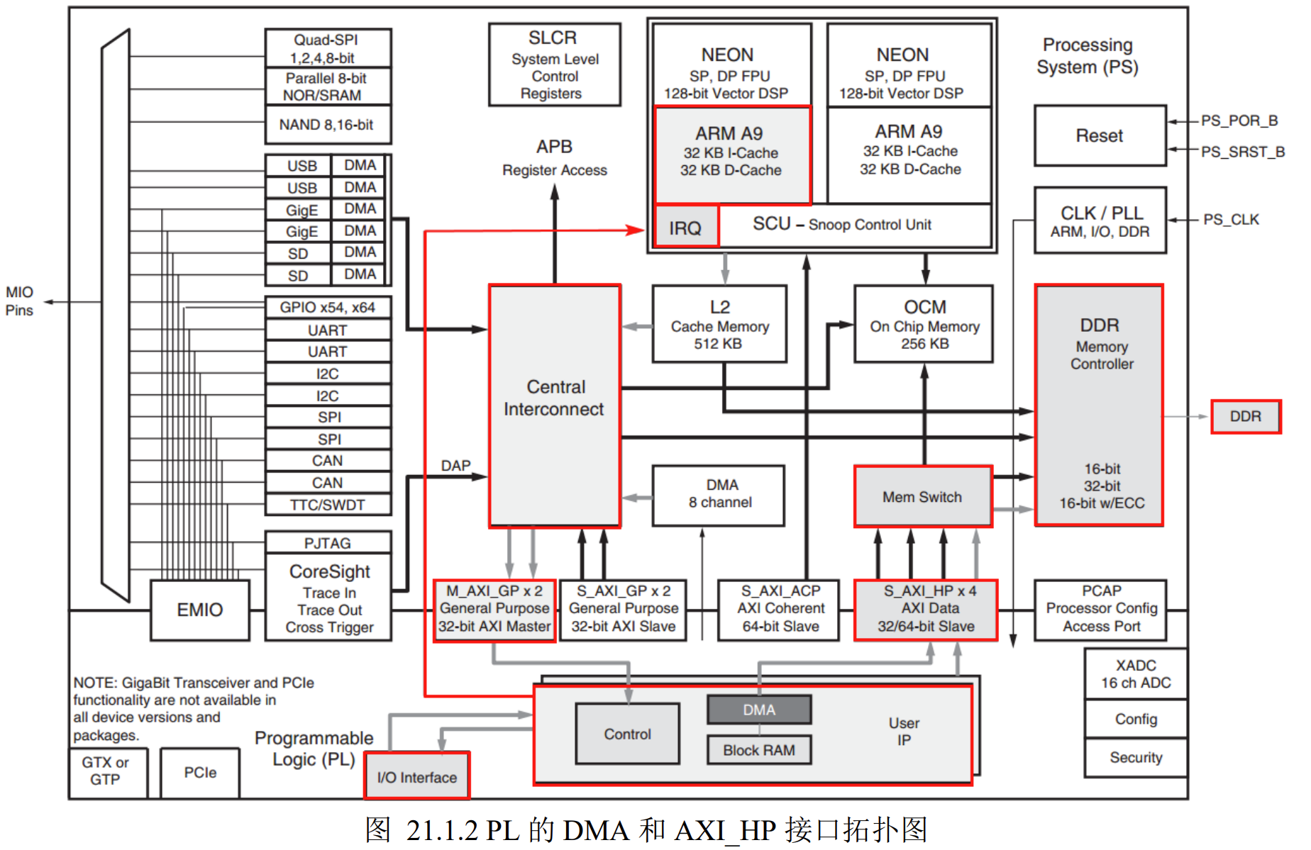
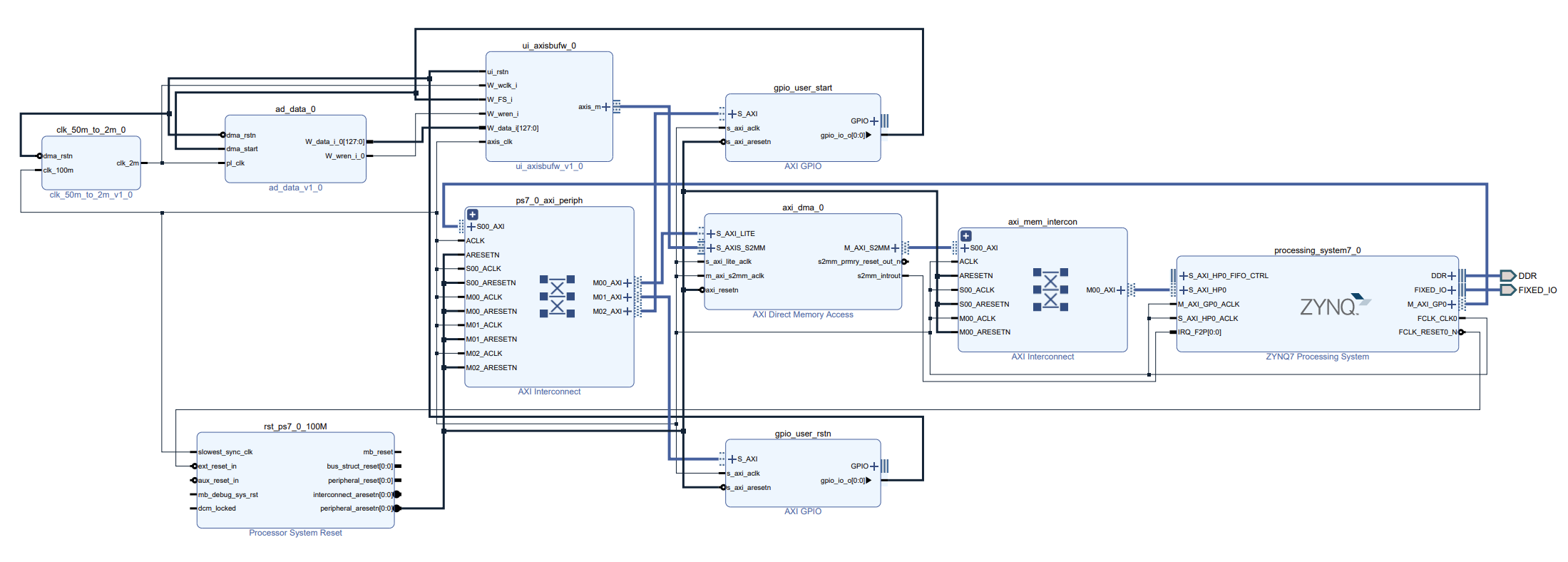
系统结果拓扑图如图所示,对 DMA 的控制或配置通过 M_AXI_GP 接口 ,而 DMA 控制的数据传输则是通过 M_AXI_HP接口
DMA AXI 软核
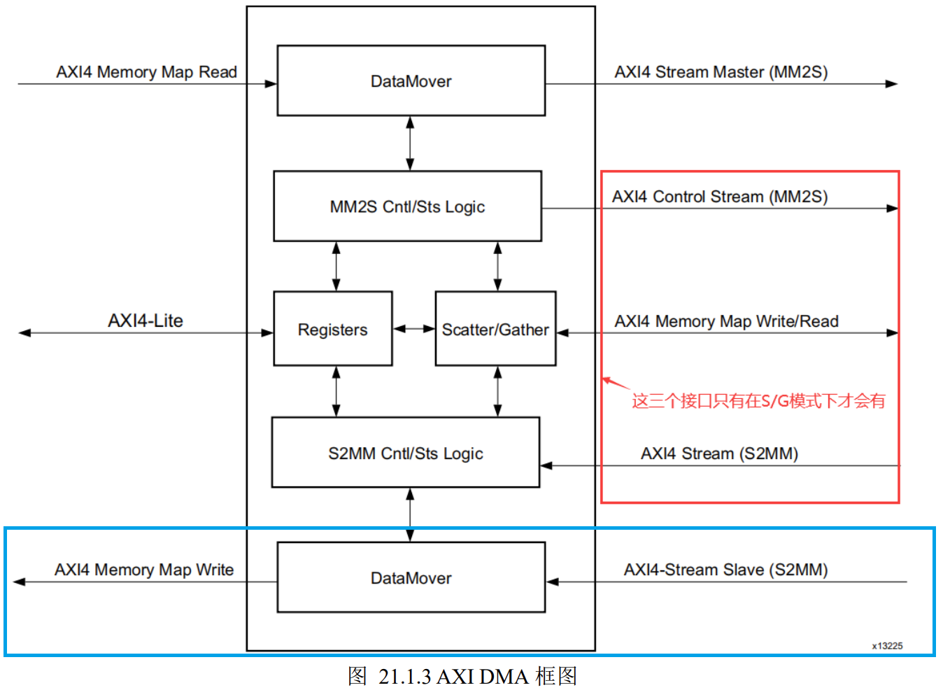
AXI DMA 提供 3 种模式,分别是 Direct Register 模式、Scatter/Gather 模式和 Cyclic DMA(循环 DMA)模式,一般情况下使用 Direct Register 模式即可,使用最简单,本次实验也是使用 Direct Register 模式
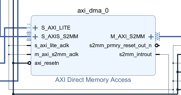
AXI DMA 的结构图如下,在本次实验中我们只需要关注蓝色方框部分内容即可,PL端数据通过S2MM(Stream to Memory Map)接口进入DMA控制器,然后通过AXI4 Memory Map Write接口通往ddr。(AXI DMA控制数据读写是双向的,可读可写的,但本次实验只使用写部分)
实验流程
Vivado部分
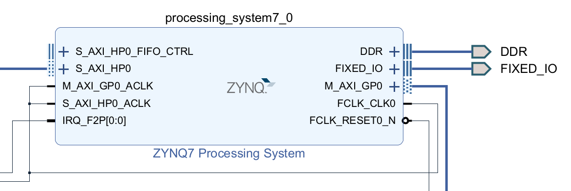
配置Zynq
开启M_AXI_GP接口用于配置,控制 AXI DMA IP
开启S_AXI_HP接口用于传输大批量数据
开启中断接口用于接收DMA传输完成后的中断信号
配置好PS DDR
配置好提供PL端的时钟和复位信号
配置AXI DMA
AXI DMA的配置界面如下,值得注意的是参数Width of Buffer Length Register代表一次DMA传输的字节量,这里23表示2的23次方,即8MB。下面因为只用写数据,所以只开启了写通道。
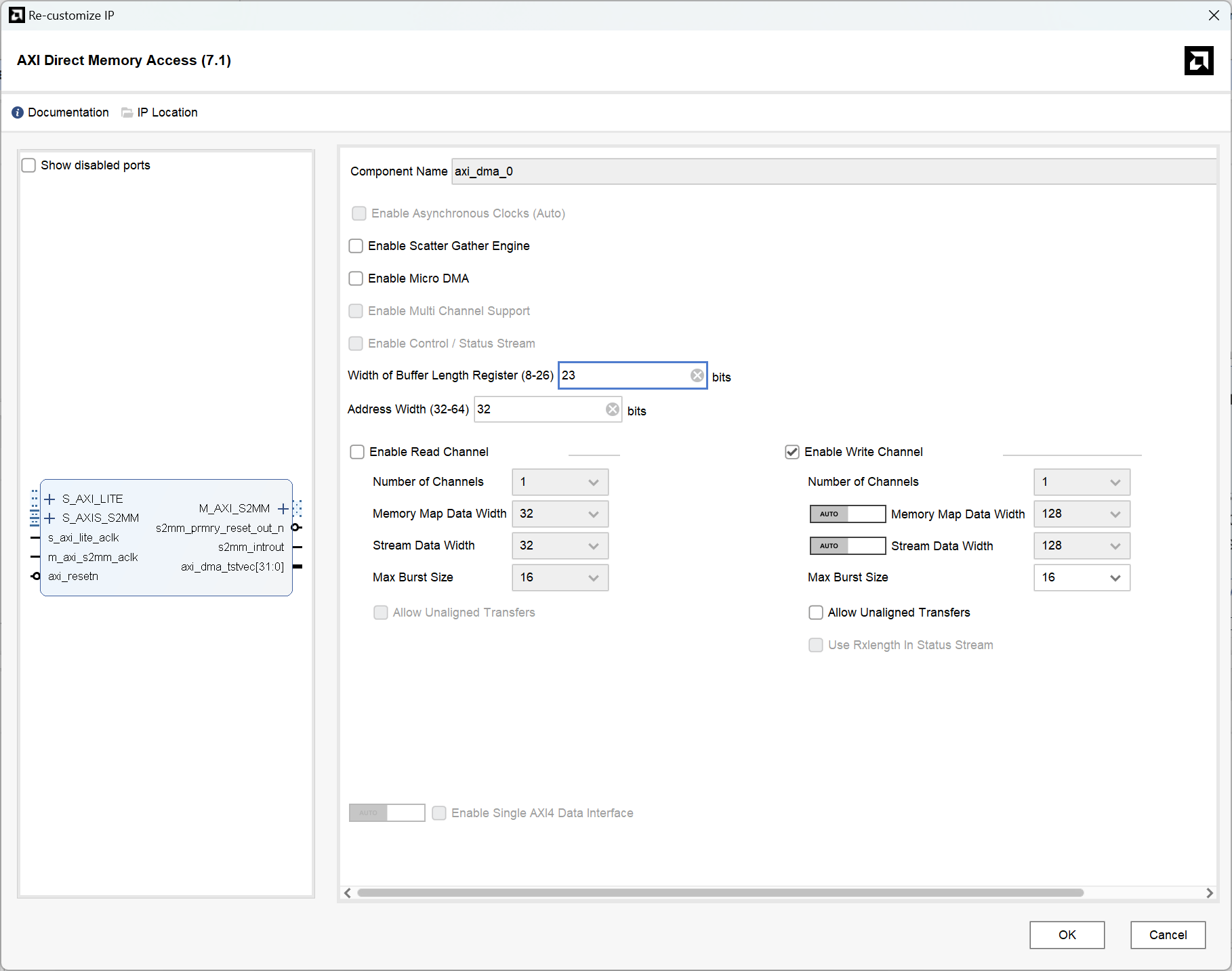
PL端数据从S_AXI_S2MM端口进入AXI DMA,然后从M_AXI_S2MM输出,值得一提的是,S2MM接口只接受AXI Stream形式的数据输入,所以PL数据应该首先进入一个AXI Stream Data FIFO缓冲再进入AXI DMA。
数据产生与转换
如下图,ad_data_0用于模拟AD数据读取的情形,将8个通道 8x16位=128位数据写入ui_axisbufw_0模块,后一个模块里面是一个FIFO,用于将数据转换为能够写入AXI DMA的形式
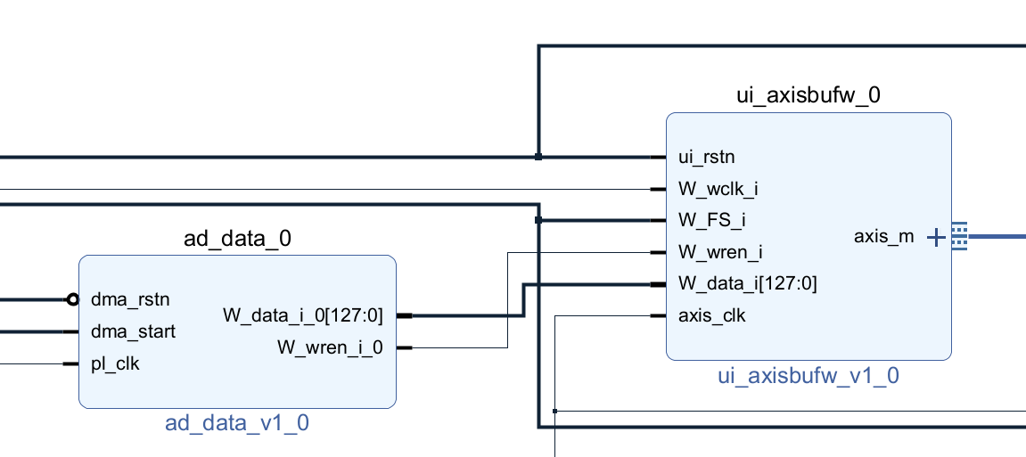
ad_data_0的细节如下,功能为产生8个16位数据,为了模拟AD采集的情况,每个通道的数据以2M时钟(模拟2M采样率)的频率增加16'h1111
`timescale 1 ps / 1 ps

module ad_data
(
	output wire [127:0]W_data_i_0,
	output wire W_wren_i_0,
	input dma_rstn,
	input dma_start,
	input pl_clk
);
reg [15:0] ad_ch0,ad_ch1,ad_ch2,ad_ch3,ad_ch4,ad_ch5,ad_ch6,ad_ch7;

assign W_data_i_0 = {ad_ch7,ad_ch6,ad_ch5,ad_ch4,ad_ch3,ad_ch2,ad_ch1,ad_ch0};
assign W_wren_i_0 = dma_start;

//模拟采集数据
always @(posedge pl_clk)begin
    if(dma_rstn == 1'b0) begin
         ad_ch0 = 16'h0000;
         ad_ch1 = 16'h1111;
         ad_ch2 = 16'h2222;
         ad_ch3 = 16'h3333;
         ad_ch4 = 16'h4444;
         ad_ch5 = 16'h5555;
         ad_ch6 = 16'h6666;
         ad_ch7 = 16'h7777;
     end
    else if(dma_start) begin
        ad_ch0<=ad_ch0+16'h1111;
        ad_ch1<=ad_ch1+16'h1111;
        ad_ch2<=ad_ch2+16'h1111;
        ad_ch3<=ad_ch3+16'h1111;
        ad_ch4<=ad_ch4+16'h1111;
        ad_ch5<=ad_ch5+16'h1111;
        ad_ch6<=ad_ch6+16'h1111;
        ad_ch7<=ad_ch7+16'h1111;
        if(ad_ch0 == 16'hffff)
            ad_ch0 <= 16'h0000;
        else if(ad_ch1 == 16'hffff)
            ad_ch1 <= 16'h0000;
        else if(ad_ch2 == 16'hffff)
            ad_ch2 <= 16'h0000;
        else if(ad_ch3 == 16'hffff)
            ad_ch3 <= 16'h0000;
        else if(ad_ch4 == 16'hffff)
            ad_ch4 <= 16'h0000;
        else if(ad_ch5 == 16'hffff)
            ad_ch5 <= 16'h0000;
        else if(ad_ch6 == 16'hffff)
            ad_ch6 <= 16'h0000;
        else if(ad_ch7 == 16'hffff)
            ad_ch7 <= 16'h0000;
    end
end

endmodule
整体设计
其余还有些细节不再详述,最后的系统总结构如图所示
然后就是Generate Output Products和Create HDL Wrapper,最后产生Bistream,导出xsa文件。
Vitis部分
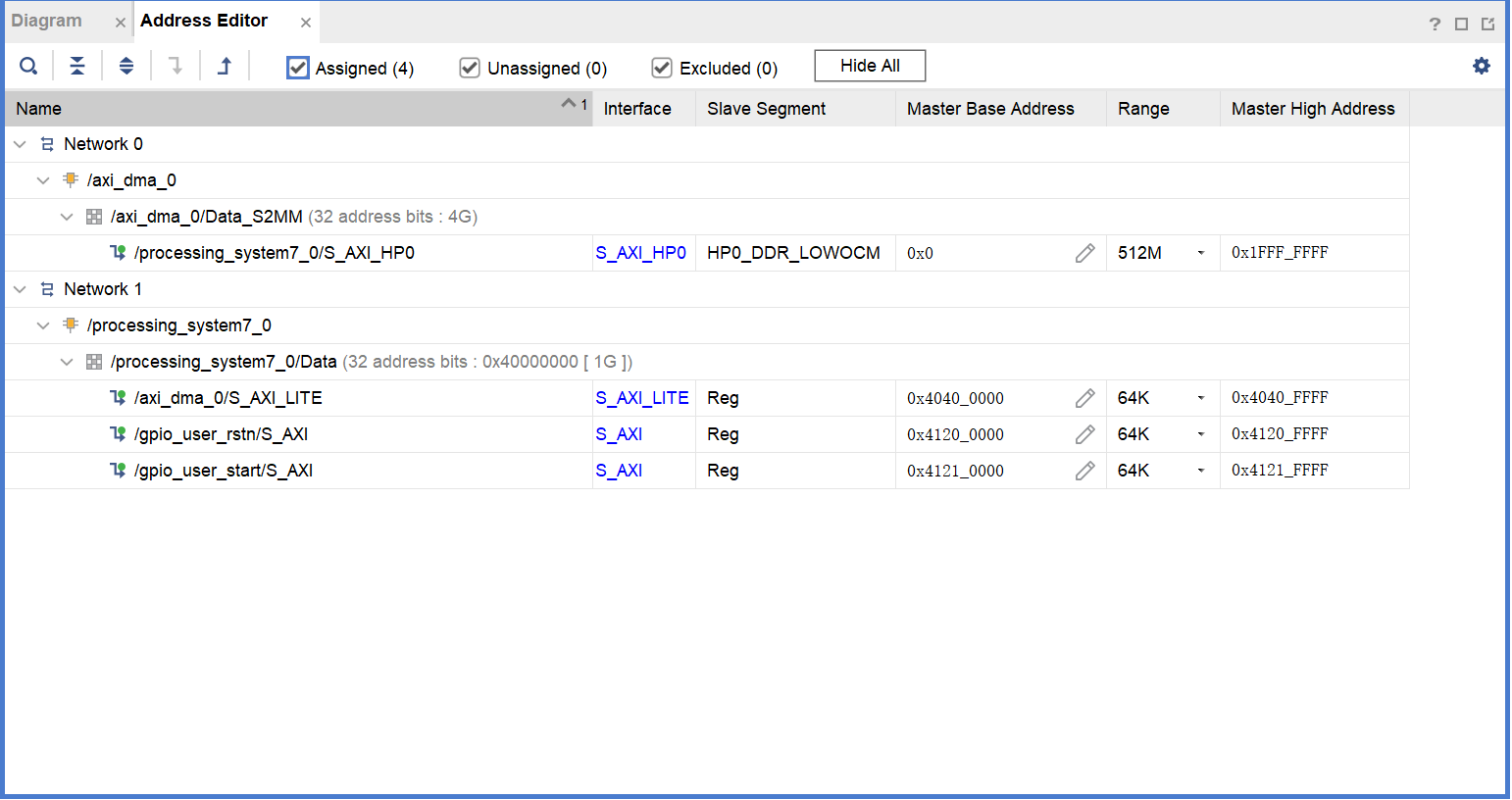
在Vivado部分中dma设定的地址范围如图所示,可以看到范围为0x0000_0000到0x1FFF_FFFF
代码定义了很多参数:
一次DMA传输的字节数为4MB(上文提到AXI DMA配置为一次传输最大为8MB,即这里可配置为小于等于8MB的任意字节数)
数据写入的地址是在这里确定的,为0x0800_0000,一次DMA传输写入4MB内存,如果还要继续写入,则需要多次DMA传输,这里设置最多传输16次,然后又会重新开始,即从0x0800_0000开始最多写64MB,到0x0C00_0000 ,然后的下一次DMA传输又将数据写回0x0800_0000
整体代码如下
#include "xparameters.h"
#include "xil_exception.h"
#include "xdebug.h"
#include "xscugic.h"
#include "xgpio.h"
#include "xaxidma.h"

/*----------System Intr define----------*/
#define INTC_DEVICE_ID          XPAR_SCUGIC_SINGLE_DEVICE_ID

int Init_Intr_System(XScuGic * IntcInstancePtr);
void Setup_Intr_Exception(XScuGic * IntcInstancePtr);

/*----------DMA Intr define----------*/
/*
 * Device hardware build related constants.
 */
#define DMA_DEV_ID			XPAR_AXIDMA_0_DEVICE_ID
#define RX_INTR_ID			XPAR_FABRIC_AXI_DMA_0_S2MM_INTROUT_INTR
#define RX_BUFFER_BASE		0x08000000
#define RESET_TIMEOUT_COUNTER	10000
#define MAX_PKT_LEN		1024*1024*4//4M

void DMA_DisableIntrSystem(XScuGic * IntcInstancePtr, u16 RxIntrId);
int  DMA_Setup_Intr_System(XScuGic * IntcInstancePtr,XAxiDma * AxiDmaPtr,  u16 RxIntrId);
int  DMA_Intr_Enable(XScuGic * IntcInstancePtr,XAxiDma *DMAPtr);
int  DMA_Intr_Init(XAxiDma *DMAPtr,u32 DeviceId);

/*----------main define----------*/

XAxiDma AxiDma;
XScuGic Intc; //GIC
XGpio gpio_user_rstn;
XGpio gpio_user_start;

u32 RxBufferPtr[16];

extern volatile int RxDone;
extern volatile int Error;

volatile u32 pkg_cnt;
volatile u32 first_transmit;
volatile u32 pkg_cntkg_cnt=0;
u32 i=0;
static void printDDR(int BaseAddr,int len);
void gpio_init(void)
{
	XGpio_Initialize(&gpio_user_rstn, XPAR_GPIO_USER_RSTN_DEVICE_ID);
	XGpio_SetDataDirection(&gpio_user_rstn, 1, 0x0);
	XGpio_DiscreteWrite(&gpio_user_rstn,1,0x0);

	XGpio_Initialize(&gpio_user_start, XPAR_GPIO_USER_START_DEVICE_ID);
	XGpio_SetDataDirection(&gpio_user_start, 1, 0x0);

	XGpio_DiscreteWrite(&gpio_user_rstn,1,0x1);//reset done
}
void dma_wr_set(u32 set)
{
	if(set==0)
		XGpio_DiscreteWrite(&gpio_user_start, 1, 0x0);//start dma
	else
		XGpio_DiscreteWrite(&gpio_user_start, 1, 0x1);//start dma
}

int axi_dma_test()
{

	u32 Status;
	pkg_cnt = 0;
	RxDone = 0;
	first_transmit =1;

	//initialize buffer address
	for(i=0;i<16;i++)
	{
		RxBufferPtr[i] = RX_BUFFER_BASE + 0x00400000*i;
	}

	if(first_transmit)dma_wr_set(1);//start dma

	//dma to ddr 16 times
	while(1)
	{
		if(first_transmit)
		{
			Status = XAxiDma_SimpleTransfer(&AxiDma,(u32)RxBufferPtr[pkg_cnt],(u32)(MAX_PKT_LEN), XAXIDMA_DEVICE_TO_DMA);

			first_transmit = 0;
		}

		else if(RxDone && pkg_cnt <15 )
		{
			RxDone =0;

			Status = XAxiDma_SimpleTransfer(&AxiDma,(u32)RxBufferPtr[pkg_cnt+1],(u32)(MAX_PKT_LEN), XAXIDMA_DEVICE_TO_DMA);

		    Xil_DCacheInvalidateRange((u32)RxBufferPtr[pkg_cnt], MAX_PKT_LEN);

		    pkg_cnt++;
		}

		else if(RxDone && pkg_cnt ==15)
		{
			Xil_DCacheInvalidateRange((u32)RxBufferPtr[pkg_cnt], MAX_PKT_LEN);

			RxDone =0;

			pkg_cnt = 0;

			dma_wr_set(0);//stop

			first_transmit = 1;

			DMA_Intr_Init(&AxiDma,0);

			dma_wr_set(1);//restart
		}
		printDDR((u32)RxBufferPtr[pkg_cnt],(u32)(MAX_PKT_LEN));
	}

	return XST_SUCCESS;

}

int init_intr_sys(void)
{
	DMA_Intr_Init(&AxiDma,0);//initial interrupt system
	Init_Intr_System(&Intc); // initial DMA interrupt system
	Setup_Intr_Exception(&Intc);
	DMA_Setup_Intr_System(&Intc,&AxiDma,RX_INTR_ID);//setup dma interrpt system
	DMA_Intr_Enable(&Intc,&AxiDma);
	return 0;
}

int main(void)
{
	xil_printf("---   PL to PS test   ---\r\n");
	gpio_init();
	init_intr_sys();
	axi_dma_test();
}

static void printDDR(int BaseAddr,int len){
	//要等2秒再开始打印,不然数据还未刷新就被读取然后串口发送了
	usleep(2000*1000);
	int i;
	xil_printf("---   print DDR   ---\r\n");
	for(i=0;i<len;i+=2){
		if(i==0||i%16==0){
			xil_printf("\r\npackage %d: ",i/16);
		}
		xil_printf("%04x  ",(int)(Xil_In16(BaseAddr+i)));
		//每隔10ms打印1个数据,免得卡死
		usleep(1000*10);
	}
}

//sys_intr
/*****************************************************************************/
/*
*
* This function is used to set the system interrupt
*
*
* @param IntcInstancePtr is the pointer to the INTC component instance
*
*
******************************************************************************/

void Setup_Intr_Exception(XScuGic * IntcInstancePtr)
{
	/* Enable interrupts from the hardware */
	Xil_ExceptionInit();
	Xil_ExceptionRegisterHandler(XIL_EXCEPTION_ID_INT,
			(Xil_ExceptionHandler)XScuGic_InterruptHandler,
			(void *)IntcInstancePtr);

	Xil_ExceptionEnable();
}

/*****************************************************************************/
/*
*
* This function is used to set the initialize system interrupt
*
*
* @param IntcInstancePtr is the pointer to the INTC component instance
*
*
******************************************************************************/

int Init_Intr_System(XScuGic * IntcInstancePtr)
{
	int Status;

	XScuGic_Config *IntcConfig;
	/*
	 * Initialize the interrupt controller driver so that it is ready to
	 * use.
	 */
	IntcConfig = XScuGic_LookupConfig(INTC_DEVICE_ID);
	if (NULL == IntcConfig) {
		return XST_FAILURE;
	}

	Status = XScuGic_CfgInitialize(IntcInstancePtr, IntcConfig,
					IntcConfig->CpuBaseAddress);
	if (Status != XST_SUCCESS) {
		return XST_FAILURE;
	}
	return XST_SUCCESS;
}

//dma_intr
volatile int TxDone;
volatile int RxDone;
volatile int Error;
volatile int RX_success;

/*****************************************************************************/
/**
*
* This function disables the interrupts for DMA engine.
*
* @param	IntcInstancePtr is the pointer to the INTC component instance
* @param	TxIntrId is interrupt ID associated w/ DMA TX channel
* @param	RxIntrId is interrupt ID associated w/ DMA RX channel
*
* @return	None.
*
* @note		None.
*
******************************************************************************/
 void DMA_DisableIntrSystem(XScuGic * IntcInstancePtr, u16 RxIntrId)
{
#ifdef XPAR_INTC_0_DEVICE_ID
	/* Disconnect the interrupts for the DMA TX and RX channels */
	XIntc_Disconnect(IntcInstancePtr, TxIntrId);
	XIntc_Disconnect(IntcInstancePtr, RxIntrId);
#else
	//XScuGic_Disconnect(IntcInstancePtr, TxIntrId);
	XScuGic_Disconnect(IntcInstancePtr, RxIntrId);
#endif
}
/*****************************************************************************/
/*
*
* This is the DMA TX Interrupt handler function.
*
* It gets the interrupt status from the hardware, acknowledges it, and if any
* error happens, it resets the hardware. Otherwise, if a completion interrupt
* is present, then sets the TxDone.flag
*
* @param	Callback is a pointer to TX channel of the DMA engine.
*
* @return	None.
*
* @note		None.
*
******************************************************************************/
static void DMA_TxIntrHandler(void *Callback)
{

	u32 IrqStatus;
	int TimeOut;
	XAxiDma *AxiDmaInst = (XAxiDma *)Callback;

	/* Read pending interrupts */
	IrqStatus = XAxiDma_IntrGetIrq(AxiDmaInst, XAXIDMA_DMA_TO_DEVICE);

	/* Acknowledge pending interrupts */


	XAxiDma_IntrAckIrq(AxiDmaInst, IrqStatus, XAXIDMA_DMA_TO_DEVICE);

	/*
	 * If no interrupt is asserted, we do not do anything
	 */
	if (!(IrqStatus & XAXIDMA_IRQ_ALL_MASK)) {

		return;
	}

	/*
	 * If error interrupt is asserted, raise error flag, reset the
	 * hardware to recover from the error, and return with no further
	 * processing.
	 */
	if ((IrqStatus & XAXIDMA_IRQ_ERROR_MASK)) {

		Error = 1;

		/*
		 * Reset should never fail for transmit channel
		 */
		XAxiDma_Reset(AxiDmaInst);

		TimeOut = RESET_TIMEOUT_COUNTER;

		while (TimeOut) {
			if (XAxiDma_ResetIsDone(AxiDmaInst)) {
				break;
			}

			TimeOut -= 1;
		}

		return;
	}

	/*
	 * If Completion interrupt is asserted, then set the TxDone flag
	 */
	if ((IrqStatus & XAXIDMA_IRQ_IOC_MASK)) {

		TxDone = 1;
	}
}

/*****************************************************************************/
/*
*
* This is the DMA RX interrupt handler function
*
* It gets the interrupt status from the hardware, acknowledges it, and if any
* error happens, it resets the hardware. Otherwise, if a completion interrupt
* is present, then it sets the RxDone flag.
*
* @param	Callback is a pointer to RX channel of the DMA engine.
*
* @return	None.
*
* @note		None.
*
******************************************************************************/
static void DMA_RxIntrHandler(void *Callback)
{
	u32 IrqStatus;
	int TimeOut;
	XAxiDma *AxiDmaInst = (XAxiDma *)Callback;

	/* Read pending interrupts */
	IrqStatus = XAxiDma_IntrGetIrq(AxiDmaInst, XAXIDMA_DEVICE_TO_DMA);

	/* Acknowledge pending interrupts */
	XAxiDma_IntrAckIrq(AxiDmaInst, IrqStatus, XAXIDMA_DEVICE_TO_DMA);

	/*
	 * If no interrupt is asserted, we do not do anything
	 */
	if (!(IrqStatus & XAXIDMA_IRQ_ALL_MASK)) {
		return;
	}

	/*
	 * If error interrupt is asserted, raise error flag, reset the
	 * hardware to recover from the error, and return with no further
	 * processing.
	 */
	if ((IrqStatus & XAXIDMA_IRQ_ERROR_MASK)) {

		Error = 1;

		/* Reset could fail and hang
		 * NEED a way to handle this or do not call it??
		 */
		XAxiDma_Reset(AxiDmaInst);

		TimeOut = RESET_TIMEOUT_COUNTER;

		while (TimeOut) {
			if(XAxiDma_ResetIsDone(AxiDmaInst)) {
				break;
			}

			TimeOut -= 1;
		}

		return;
	}

	/*
	 * If completion interrupt is asserted, then set RxDone flag
	 */
	if ((IrqStatus & XAXIDMA_IRQ_IOC_MASK)) {

		RX_success++;
		RxDone = 1;
	}
}

/*****************************************************************************/
/*
*
* This function setups the interrupt system so interrupts can occur for the
* DMA, it assumes INTC component exists in the hardware system.
*
* @param	IntcInstancePtr is a pointer to the instance of the INTC.
* @param	AxiDmaPtr is a pointer to the instance of the DMA engine
* @param	TxIntrId is the TX channel Interrupt ID.
* @param	RxIntrId is the RX channel Interrupt ID.
*
* @return
*		- XST_SUCCESS if successful,
*		- XST_FAILURE.if not succesful
*
* @note		None.
*
******************************************************************************/
int DMA_Setup_Intr_System(XScuGic * IntcInstancePtr,XAxiDma * AxiDmaPtr, u16 RxIntrId)
{
	int Status;
	//XScuGic_SetPriorityTriggerType(IntcInstancePtr, TxIntrId, 0xA0, 0x3);

	XScuGic_SetPriorityTriggerType(IntcInstancePtr, RxIntrId, 0xA0, 0x3);
	/*
	 * Connect the device driver handler that will be called when an
	 * interrupt for the device occurs, the handler defined above performs
	 * the specific interrupt processing for the device.
	 */
	//Status = XScuGic_Connect(IntcInstancePtr, TxIntrId,
	//			(Xil_InterruptHandler)DMA_TxIntrHandler,
	//			AxiDmaPtr);
	//if (Status != XST_SUCCESS) {
	//	return Status;
	//}

	Status = XScuGic_Connect(IntcInstancePtr, RxIntrId,
				(Xil_InterruptHandler)DMA_RxIntrHandler,
				AxiDmaPtr);
	if (Status != XST_SUCCESS) {
		return Status;
	}

	//XScuGic_Enable(IntcInstancePtr, TxIntrId);
	XScuGic_Enable(IntcInstancePtr, RxIntrId);
	return XST_SUCCESS;
}


int DMA_Intr_Enable(XScuGic * IntcInstancePtr,XAxiDma *DMAPtr)
{

	/* Disable all interrupts before setup */

	//XAxiDma_IntrDisable(DMAPtr, XAXIDMA_IRQ_ALL_MASK,
	//					XAXIDMA_DMA_TO_DEVICE);

	XAxiDma_IntrDisable(DMAPtr, XAXIDMA_IRQ_ALL_MASK,
				XAXIDMA_DEVICE_TO_DMA);

	/* Enable all interrupts */
	//XAxiDma_IntrEnable(DMAPtr, XAXIDMA_IRQ_ALL_MASK,
	//						XAXIDMA_DMA_TO_DEVICE);

	XAxiDma_IntrEnable(DMAPtr, XAXIDMA_IRQ_ALL_MASK,
							XAXIDMA_DEVICE_TO_DMA);
	return XST_SUCCESS;

}


int DMA_Intr_Init(XAxiDma *DMAPtr,u32 DeviceId)
{
	int Status;
	XAxiDma_Config *Config=NULL;

	Config = XAxiDma_LookupConfig(DeviceId);
	if (!Config) {
		xil_printf("No config found for %d\r\n", DeviceId);
		return XST_FAILURE;
	}

	/* Initialize DMA engine */
	Status = XAxiDma_CfgInitialize(DMAPtr, Config);

	if (Status != XST_SUCCESS) {
		xil_printf("Initialization failed %d\r\n", Status);
		return XST_FAILURE;
	}

	if(XAxiDma_HasSg(DMAPtr)){
		xil_printf("Device configured as SG mode \r\n");
		return XST_FAILURE;
	}
	return XST_SUCCESS;

}
测试结果
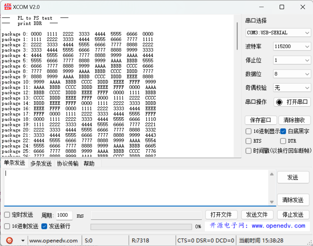
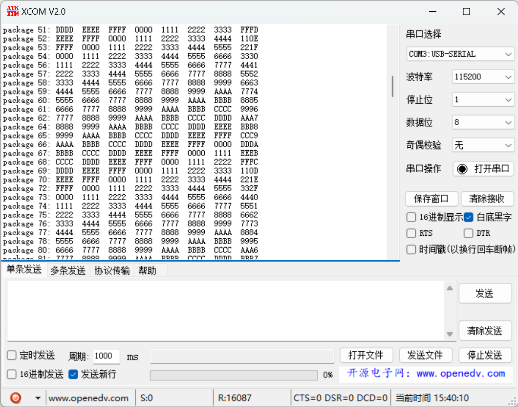
串口打印的数据如图所示,以8个通道一组打印数据
可以看到前7个通道的数据是没有任何问题的,但第8个通道的数据一开始就不正确,应该为7777,然后再逐渐累加1111的时候也会发现数据错乱,问题待解决
本文章使用limfx的vscode插件快速发布