Zynq Linux axi_lite控制led
这个实验的关键是涉及到PL端外设的控制,比较完整的走了一次Vivado开发;Vitis开发;虚拟机产生启动文件,设备树;虚拟机驱动开发;最后上板验证的过程
在开发流程上比较有参考价值
实验目的
通过Linux命令行控制开发板上PL端两个LED灯的亮灭情况
实验流程
Vivado开发部分
这部分可以参考 https://www.limfx.pro/ReadArticle/3648/chuan-kou-kong-zhi-led-shan-shuo-ke-tiao-pin-lv 的Vivado部分
这部分流程也很熟悉了,就是创建Block Design,先添加Zynq IP核配置,然后添加AXI LITE IP核,配置为slave,4个寄存器里用1个,引出引脚控制两个led,保存AXI LITE IP核
然后回到Block Design,自动连线,Generate Output Products和Create HDL Wrapper,最后产生Bitstream,导出xsa
Vitis部分
这部分是要将刚才导出的xsa创建成一个平台工程
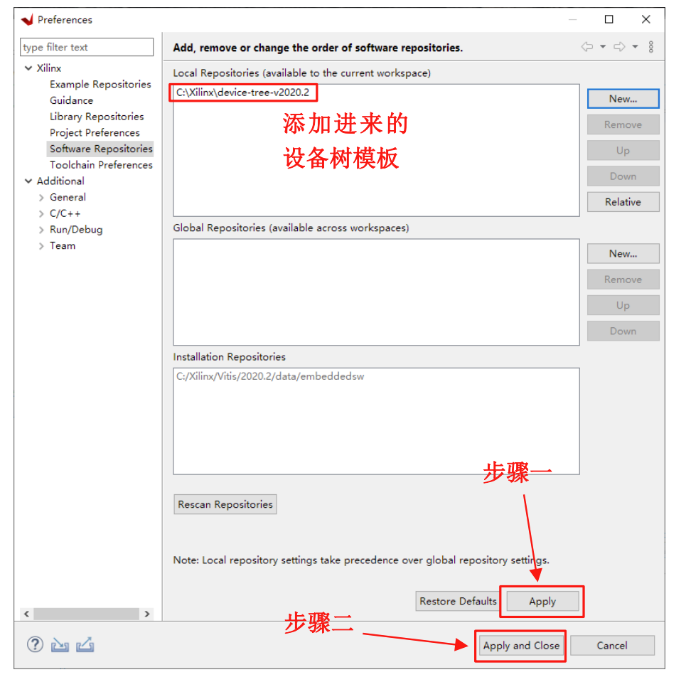
打开Vitis,添加设备树文件
创建平台工程
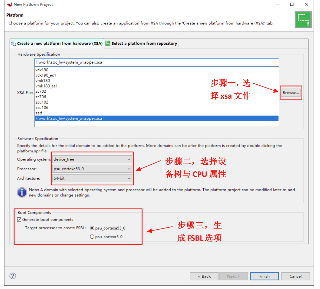
创建好后直接编译,编译好后找到三个文件,传到虚拟机用
system_wrapper.bit: {工程位置}\zu_sdk\zu_base\hw
fsbl.elf: {工程位置}\zu_sdk\zu_base\export\zu_base\sw\zu_base\boot
pmufw.elf: {工程位置}\zu_sdk\zu_base\export\zu_base\sw\zu_base\boot\
将 system_wrapper.bit、fsbl.elf 两个文件分别改名为 system.bit、zynqmp_fsbl.elf,打开虚拟机, 然后将 system.bit 、 zynqmp_fsbl.elf 、 pmufw.elf 三个文件拷贝到
{解压目录}/uisrc-lab-xlnx/boards/mzux/ubuntu/output/target
然后找到设备树文件 pl.dtsi ,在 {工程位置}\psu_cortexa53_0\device_tree_domain\bsp\ 下
将里面的内容复制到 zynqmp-mzux.dtsi中(这个文件第一次制作linux镜像时有提供)
/ {
	amba_pl: amba_pl@0 {
		#address-cells = <2>;
		#size-cells = <2>;
		compatible = "simple-bus";
		ranges ;
		GPIO_LITE_ML_v1_0_0: GPIO_LITE_ML_v1_0@80000000 {
			/* This is a place holder node for a custom IP, user may need to update the entries */
			clock-names = "s00_axi_aclk";
			clocks = <&zynqmp_clk 71>;
			compatible = "xlnx,GPIO-LITE-ML-v1-0-1.0";
			reg = <0x0 0x80000000 0x0 0x10000>;
			xlnx,s00-axi-addr-width = <0x4>;
			xlnx,s00-axi-data-width = <0x20>;
		};
	};
};
就是说pl端修改了内容,会影响这里 pl.dtsi 文件的改变,然后再复制到 zynqmp-mzux.dtsi 中
将zynqmp-mzux.dtsi 分别复制到
{解压目录}/uisrc-linuxb/sources/uboot/arch/arm/dts
{解压目录}/uisrc-linuxb/sources/kernel/arch/arm64/boot/dts/xilinx
这里看到,PL部分的修改需要fsbl的三个文件和设备树文件的更改,重新传输到虚拟机
然后在虚拟机开发环境中执行命令
source ./scripts/mzuxcfg.sh
make_uboot.sh
make_kernel.sh
create_image.sh
执行完后在 uisrc-lab-xlnx/boards/mzux/ubuntu/images/boot下生成三个文件
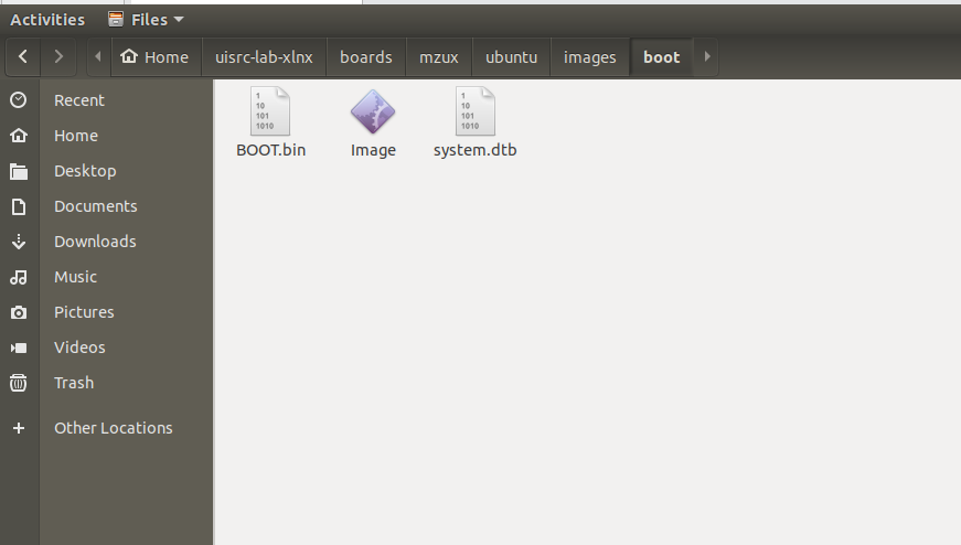
拷贝到sd卡中,将sd卡插回开发板
驱动开发
这里贴出代码,值得一提的是,驱动代码中的open,close,read,write四个函数和key_fops,key_major,key_cls等变量是和app紧密关联的,也就是说,如果要进行app的开发就要实现对应的函数,对这些变量进行初始化工作。
驱动代码 axi_user_gpio.c
#include <linux/ide.h>
#include <linux/module.h>
#include <linux/of_platform.h>
#include <linux/delay.h>

struct AxiUserGpio
{
	int addr_width;
	int data_width;
	struct device_node *dev_node;
	int reg_num;
	unsigned int *reg_value;
};
struct AxiUserGpio *AxiUserGpio_data;
static int key_major;
static struct class *key_cls;

static unsigned int *AxiData_0 = NULL;

static struct of_device_id AxiUserGpio_of_match[] = {
	{.compatible = "xlnx,GPIO-LITE-ML-v1-0-1.0"},
	{},
};

int of_AxiUserGpio_data(struct AxiUserGpio *pdata, struct platform_device *pdev)
{
	struct device_node *np = pdev->dev.of_node;
	int ret = 0;

	pdata->reg_num = of_property_count_elems_of_size(np, "reg", sizeof(int));
	if (pdata->reg_num < 0)
	{
		dev_err(&pdev->dev, "get reg_num failed\n");
		return ret;
	}

	pdata->reg_value = (unsigned int *)kmalloc(sizeof(unsigned int) * pdata->reg_num, GFP_KERNEL);
	if (!pdata->reg_value)
	{
		kfree(pdata->reg_value);
		dev_err(&pdev->dev, "kmalloc failed\n");
		return -1;
	}
	ret = of_property_read_u32_array(np, "reg", pdata->reg_value, pdata->reg_num);
	if (ret != 0)
	{
		kfree(pdata->reg_value);
		dev_err(&pdev->dev, "get reg failed\n");
		return ret;
	}

	ret = of_property_read_u32(np, "xlnx,s00-axi-addr-width", &pdata->addr_width);
	if (ret < 0)
	{
		dev_err(&pdev->dev, "get addr_width failed\n");
		return ret;
	}

	ret = of_property_read_u32(np, "xlnx,s00-axi-data-width", &pdata->data_width);
	if (ret < 0)
	{
		dev_err(&pdev->dev, "get data_width failed\n");
		return ret;
	}

	return 0;
}

static int AxiUserGpio_probe(struct platform_device *pdev)
{
	int ret = 0;
	int i = 0;

	struct device *dev = &pdev->dev;
	struct AxiUserGpio *pdata = dev_get_platdata(dev);
	if (!pdata)
	{
		pdata = devm_kzalloc(dev, sizeof(struct AxiUserGpio), GFP_KERNEL);
		if (!pdata)
			return -ENOMEM;

		platform_set_drvdata(pdev, pdata);
	}
	ret = of_AxiUserGpio_data(pdata, pdev);
	AxiUserGpio_data = pdata;

	// 打印属性值
	printk("addr_width = %d\r\n", AxiUserGpio_data->addr_width);
	printk("data_width = %d\r\n", AxiUserGpio_data->data_width);
	printk("reg_num = %d\r\n", AxiUserGpio_data->reg_num);
	for (i = 0; i < AxiUserGpio_data->reg_num; i += 2)
	{
		printk("reg = %#X  %#X \r\n", AxiUserGpio_data->reg_value[i], AxiUserGpio_data->reg_value[i + 1]);
	}
	AxiData_0 = ioremap(AxiUserGpio_data->reg_value[1] + AxiUserGpio_data->addr_width * 0, AxiUserGpio_data->addr_width);
	return ret;
}

static int AxiUserGpio_remove(struct platform_device *pdev)
{
	kfree(AxiUserGpio_data->reg_value);
	iounmap(AxiData_0);
	return 0;
}

int AxiUserGpio_open(struct inode *inode, struct file *filp)
{
	printk("axi gpio open\n");
	return 0;
}
ssize_t AxiUserGpio_read(struct file *filp, char __user *buf, size_t count, loff_t *fops)
{
	int value[2] = {0};
	int read_data=readl(AxiData_0);
	int mask=1;
	value[0]=(read_data>>1)&mask;
	value[1]=read_data&mask;
	int ret = copy_to_user(buf, value, count);
	if (ret < 0)
	{
		printk("gpio get value failed!\n");
		return ret;
	}

	return 0;
}
ssize_t AxiUserGpio_write(struct file *filp, const char __user *buf, size_t count, loff_t *fops) //用户发送,内核读取信息并打印
{
	int flag = 0;
	char writebuf[2]="00";
	flag = copy_from_user(writebuf, buf, count); //使用copy_from_user读取用户态发送过来的数据
	int write_data=(writebuf[0]-'0')*2 + writebuf[1]-'0';
	if (flag == 0)
	{
		printk(KERN_CRIT "Kernel receive data: %s\n", writebuf);
	}
	else
	{
		printk("Kernel receive data failed!\n");
	}
	writel(write_data, AxiData_0);
	printk("-led write-\n");
	return 0;
}

int AxiUserGpio_close(struct inode *inode, struct file *filp)
{
	printk("axi gpio close\n");
	return 0;
}

const struct file_operations key_fops = {
	.open = AxiUserGpio_open,
	.read = AxiUserGpio_read,
	.write = AxiUserGpio_write,
	.release = AxiUserGpio_close,
};

static struct platform_driver AxiUserGpio_device_driver = {
	.driver = {
		.name = "AxiUserGpio",
		.owner = THIS_MODULE,
		.of_match_table = of_match_ptr(AxiUserGpio_of_match),
	},
	.probe = AxiUserGpio_probe,
	.remove = AxiUserGpio_remove,
};

static int __init AxiUserGpio_init(void)
{
	key_major = register_chrdev(0, "axi_gpio_led", &key_fops);
	if (key_major < 0)
	{
		printk("register chrdev faile!\n");
		return key_major;
	}
	printk("register chrdev ok!\n");

	key_cls = class_create(THIS_MODULE, "key_class");
	printk("class create ok!\n");

	device_create(key_cls, NULL, MKDEV(key_major, 0), NULL, "gpio_led%d", 0);
	printk("device create ok!\n");
	return platform_driver_register(&AxiUserGpio_device_driver);
}

static void __exit AxiUserGpio_exit(void)
{
	device_destroy(key_cls, MKDEV(key_major, 0));
	//删除类
	class_destroy(key_cls);
	//注销主设备号
	unregister_chrdev(key_major, "axi_gpio_led");
	platform_driver_unregister(&AxiUserGpio_device_driver);
}

late_initcall(AxiUserGpio_init);
module_exit(AxiUserGpio_exit);

MODULE_LICENSE("GPL");
MODULE_AUTHOR("uisrc");
应用代码 axi_user_app.c
#include <stdio.h>
#include <stdlib.h>
#include <sys/types.h>
#include <sys/stat.h>
#include <fcntl.h>
#include <unistd.h>

int main(int argc, char *argv[])
{
	int fd = 0;
	int retvalue = 0;
	int i = 0;
	int a[2] = {0};
	char writebuf[2]="00";
	fd = open("/dev/gpio_led0", O_RDWR);
	if (fd < 0)
	{
		perror("open fail!\n");
		exit(1);
	}
	switch (*argv[1]) //对操作数进行解析
	{
	case 'r':
		if (argc != 2) //进行鲁棒性检查
		{
			printf("Unknow operation, use the formate: ./APPNAME /dev/DRIVENAME r to read date from kernel.\n");
			return -1;
		}
		read(fd, a, sizeof(a));
		printf("led0 value %d\n", a[0]);
		printf("led1 value %d\n", a[1]);
		break;
	case 'w':
		if (argc != 3) //进行鲁棒性检查
		{
			printf("Unknow operation, use the formate: ./APPNAME /dev/DRIVENAME w \"USERDATE\" to write date to kernel.\n");
			return -2;
		}
		memcpy(writebuf, argv[2], strlen(argv[2])); //将内容拷贝到缓冲区
		retvalue = write(fd, writebuf, 2);			//写数据
		if (retvalue < 0)
		{
			printf("Write led failed!\n");
		}
		else
		{
			printf("Write led success!\n");
		}
		break;
	default:
		printf("Unknow Operation: %d\n", *argv[1]);
		break;
	}

	close(fd);

	return 0;
}
Makefile
#已经编译过的内核源码路径
KERNEL_DIR = /home/uisrc/uisrc-lab-xlnx/sources/kernel

export ARCH=arm64
export CROSS_COMPILE=aarch64-linux-gnu-

#当前路径
CURRENT_DIR = $(shell pwd)
APP = axi_user_app
all :
#进入并调用内核源码目录中Makefile的规则, 将当前的目录中的源码编译成模块
	make -C $(KERNEL_DIR) M=$(CURRENT_DIR) modules
ifneq ($(APP), )
	$(CROSS_COMPILE)gcc $(APP).c -o $(APP)
endif

clean :
	make -C $(KERNEL_DIR) M=$(CURRENT_DIR) clean

#指定编译哪个文件
obj-m += axi_user_gpio.o
然后传到虚拟机开发环境,交叉编译,得到axi_user_gpio.ko与axi_user_app
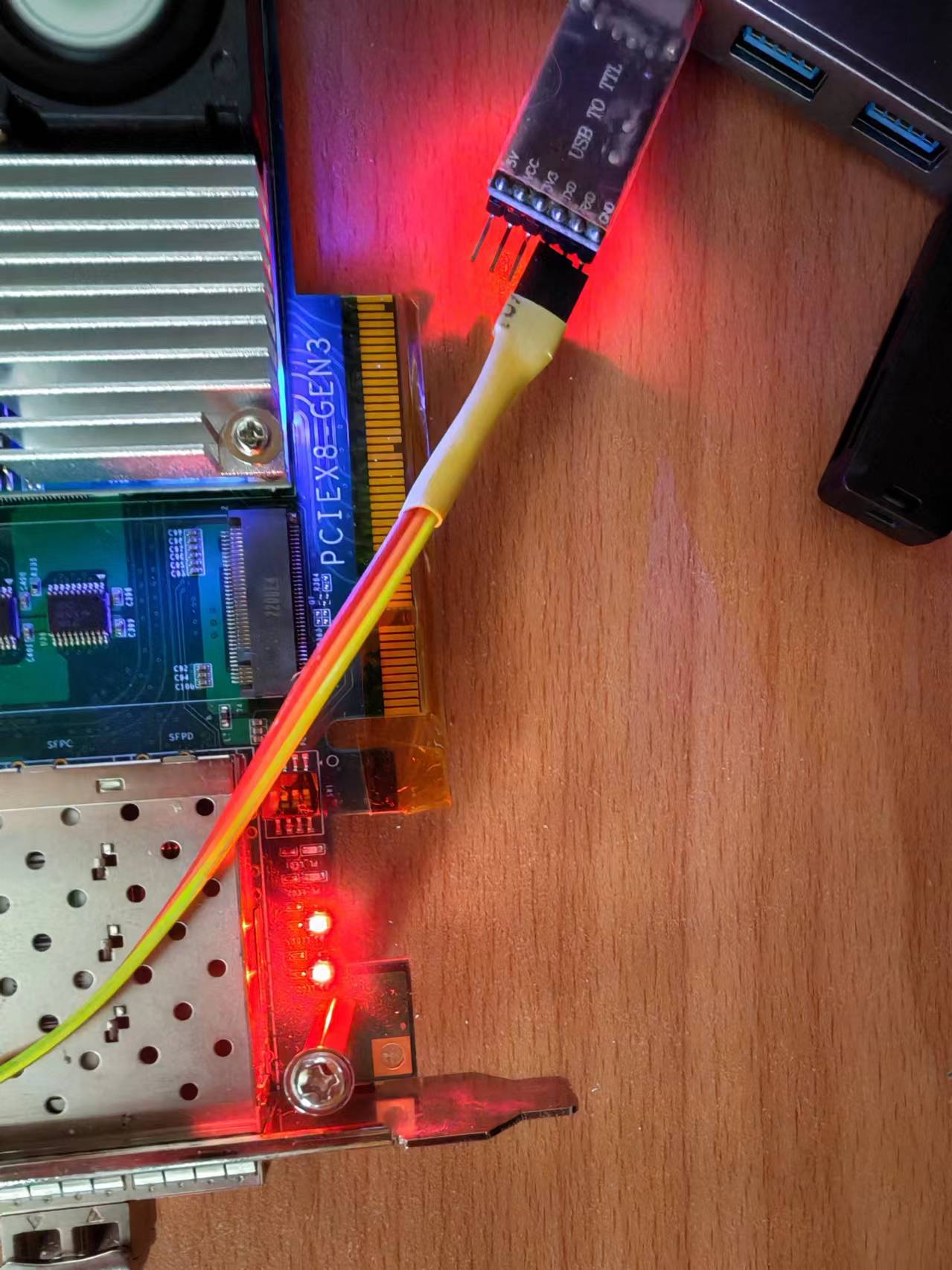
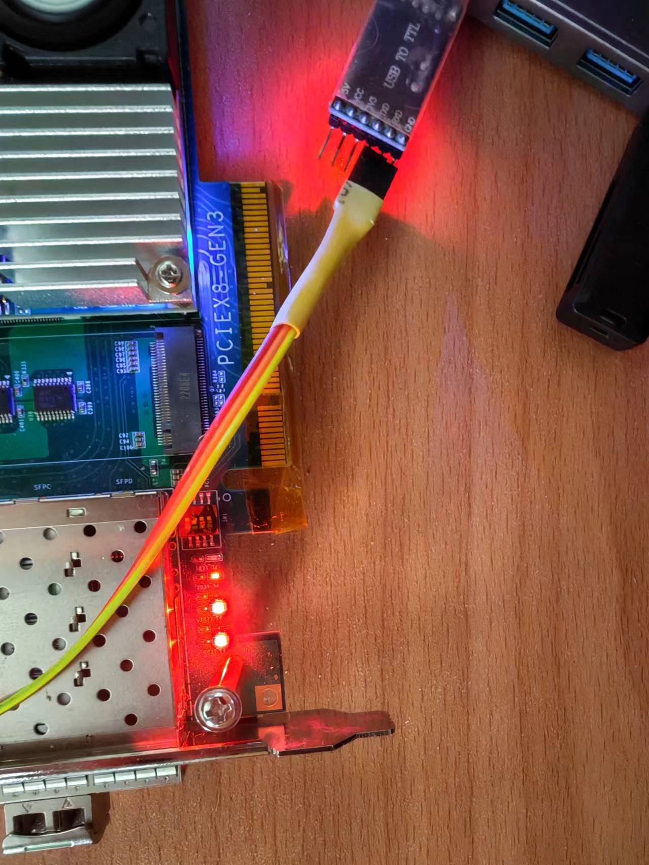
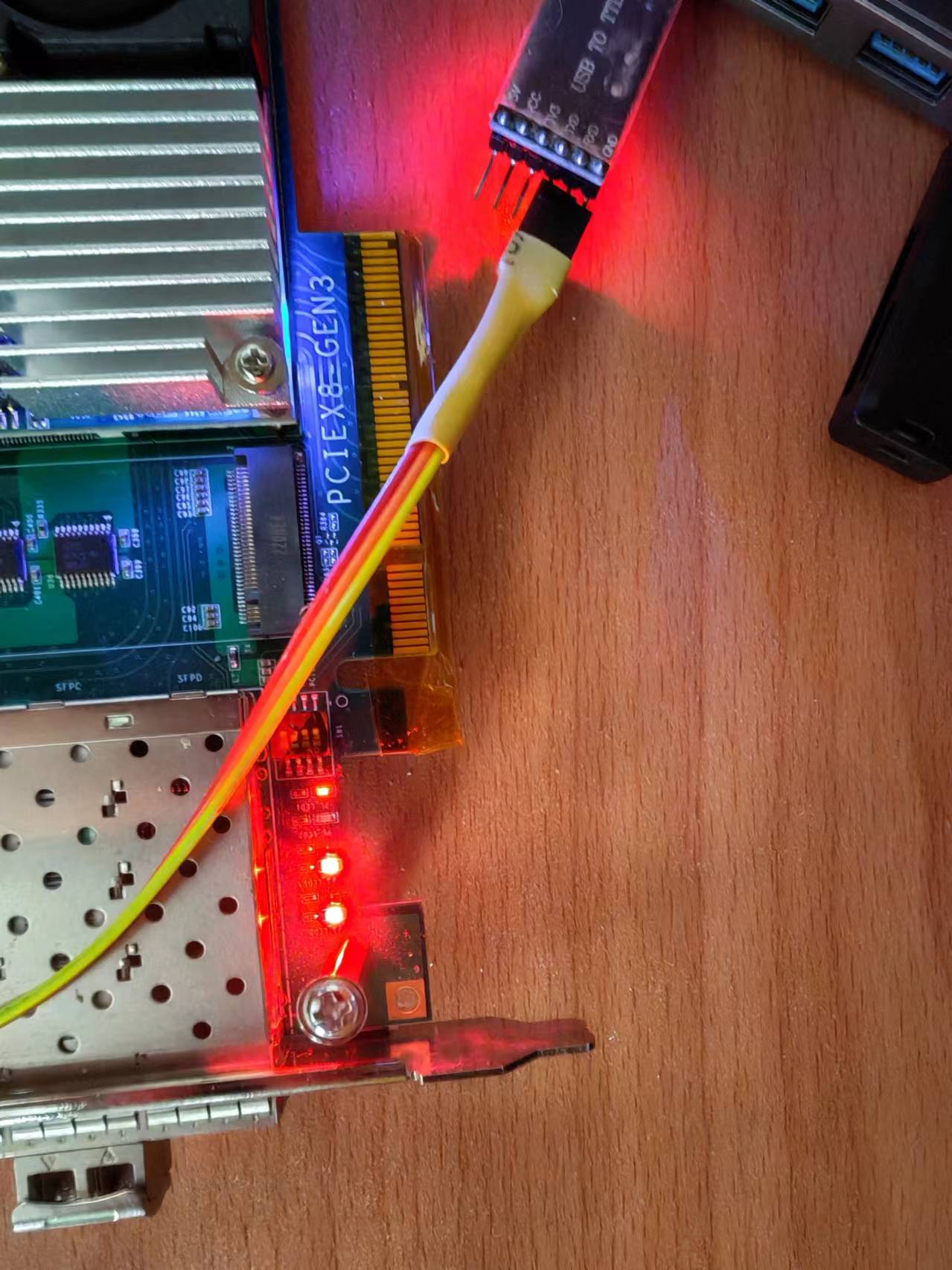
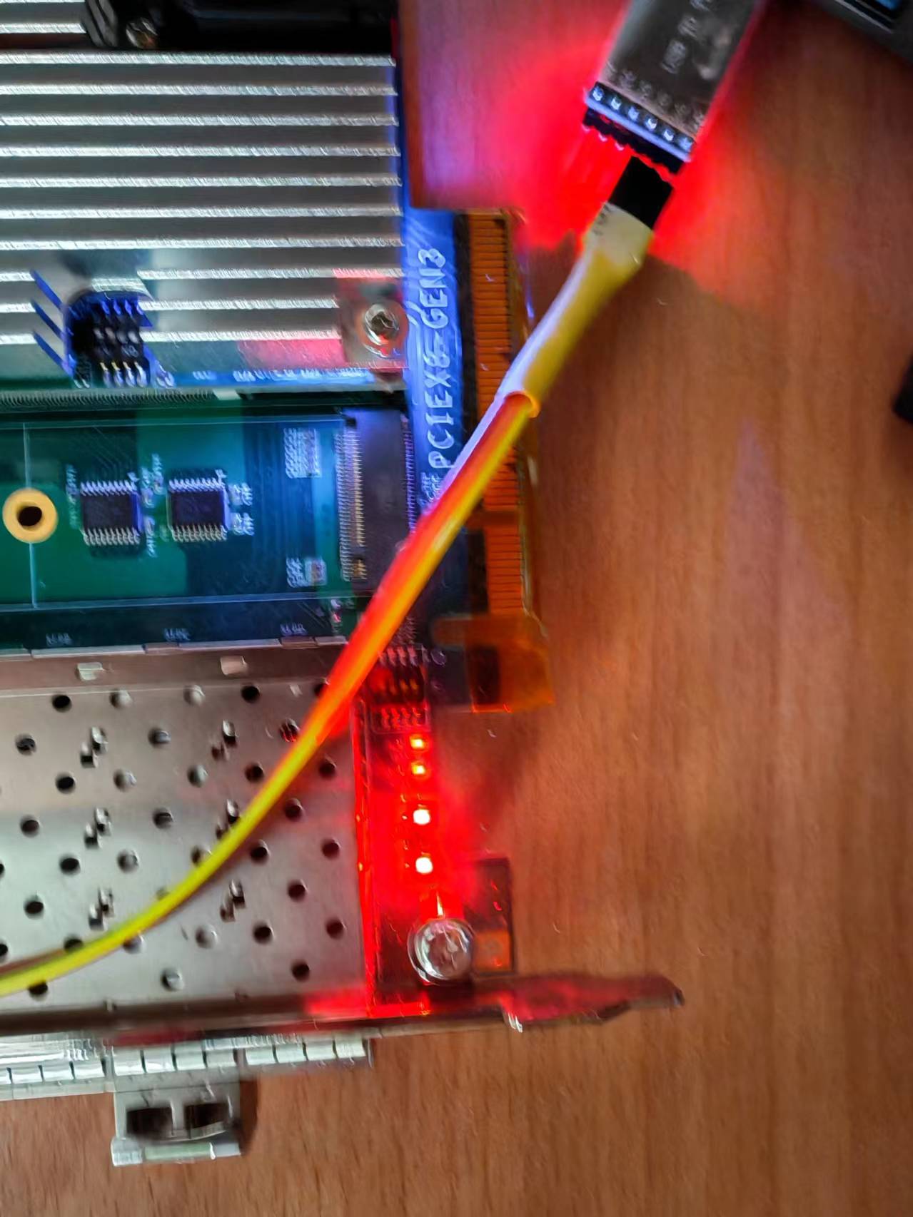
上板验证
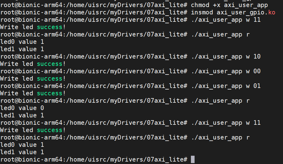
将两个文件传到开发板,验证功能,Linux命令行可以控制led亮灭变化
命令分为读和写
读命令格式为
./axi_user_app r
写命令格式为,对应led灯的四种亮灭情况
./axi_user_app w 00
./axi_user_app w 01
./axi_user_app w 10
./axi_user_app w 11
PL LED
本文章使用limfx的vscode插件快速发布