Zynq Linux axi lite实验
本实验目的是模拟ps端给pl端发参数控制pl端运行的情况,实际使用的是led闪烁来演示
项目地址:http://120.55.75.228:23080/zhdyz/axi_lite_linux
实验目的
linux端通过命令行控制pl端led灯的闪烁频率和参数可修改时间,在这端时间内参数会进入锁定状态,直到这段时间后才会读入下一批写入的参数
实验流程
报错记录
Vivado报错
Spawn failed:No error
原因分析:字面意思,没有错误,但软件硬是要报错,忽略即可
Linking the ceam library to the veamMap failed. Most likely, you need to check your installation or recompile your sandbox.
原因分析:程序综合时内存空间不足,关闭电脑打开的其他程序,清理内存空间后重新运行Vivado
Vitis平台工程编译出错
原因分析:之前有篇文章讲过这个问题,但有段时间没使用axi lite了,忘记了使用 自定义axi ip核时官方自动创建的Makefile有问题,需要修改
参考:https://www.limfx.pro/ReadArticle/3646/vitis-bian-cheng-tou-wen-jian-xparametersh-wu-fa-zhao-dao
Vivado部分
实现led闪烁和参数锁存的是led_ctrl模块,代码如下
module led_ctrl(
    input wire clk,
    input wire rstn,
    input wire [15:0] led_freq,
    input wire [15:0] led_second,
    output reg led,
    output reg idle// 0表示空闲,1表示正在工作
    );
reg [31:0]sec_cnt;
reg [15:0]freq;
reg [15:0]second;
reg [15:0] locked_freq;
reg [15:0] locked_second;
//锁存freq和second
always@(posedge clk) begin
    if(rstn==1'b0) begin
        freq<=0;
        second<=0;
    end
    else if(idle==1'b0) begin
        freq<=led_freq;
        second<=led_second;
        locked_freq<=led_freq;
        locked_second<=led_second;
    end
    else begin
        freq<=locked_freq;
        second<=locked_second;
    end
end
//分频出四个时钟
reg clk1,clk2,clk3,clk4;

//idle状态控制
always@(posedge clk3) begin
    if(rstn==1'b0) begin
        idle<=1'b0;
        sec_cnt<=0;
    end
    //idle
    if(idle==1'b0) begin
        if(freq>0) idle<=1'b1;
    end
    //working
    else begin
        if(sec_cnt==second-1) begin
            idle<=1'b0;
            sec_cnt<=0;
        end
        else
            sec_cnt<=sec_cnt+1;
    end
end


reg [31:0]cnt4;
//clk4 = 2HZ
always@(posedge clk) begin
    if(rstn==1'b0) begin
        clk4<=0;
        cnt4<=0;
    end
    else begin
        if(cnt4==24999999) begin
            cnt4<=0;
            clk4<=~clk4;
        end
        else cnt4<=cnt4+1;
    end
end
//clk3 = 1HZ
always@(posedge clk4) begin
    if(rstn==1'b0)
        clk3<=0;
    else
        clk3<=~clk3;
end
//clk2 = 0.5HZ
always@(posedge clk3) begin
    if(rstn==1'b0)
        clk2<=0;
    else
        clk2<=~clk2;
end
//clk1 = 0.25HZ
always@(posedge clk2) begin
    if(rstn==1'b0)
        clk1<=0;
    else
        clk1<=~clk1;
end
always@(posedge clk) begin
    if(rstn==1'b0)
        led=1'b0;
    else if(idle==1'b0)
        led=1'b0;
    else begin
        if(freq==1) begin
            if(clk1==1)  led=1'b1;
            else         led=1'b0;
        end
        else if(freq==2) begin
            if(clk2==1)  led=1'b1;
            else         led=1'b0;
        end
        else if(freq==4) begin
            if(clk3==1)  led=1'b1;
            else         led=1'b0;
        end
        else if(freq==8) begin
            if(clk4==1)  led=1'b1;
            else         led=1'b0;
        end
    end

end
endmodule
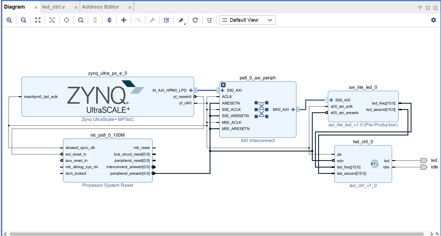
这个模块是关键,其输入的参数freq和second是从axi lite ip核中引出的,整体的block design图如下图所示,引出的led和idle引脚分别对应开发板上的两个pl端led灯
block design设计好后,生成Bitstream,导出xsa
Vitis设计部分
导入xsa,创建平台工程,获得开机启动文件和设备树文件,设备树代码如下
可以看到pl端设备树代码主要就是描述了axi lite ip核的设备信息
/ {
	amba_pl: amba_pl@0 {
		#address-cells = <2>;
		#size-cells = <2>;
		compatible = "simple-bus";
		ranges ;
		axi_lite_led_0: axi_lite_led@80000000 {
			/* This is a place holder node for a custom IP, user may need to update the entries */
			clock-names = "s00_axi_aclk";
			clocks = <&zynqmp_clk 71>;
			compatible = "xlnx,axi-lite-led-1.0";
			reg = <0x0 0x80000000 0x0 0x10000>;
			xlnx,s00-axi-addr-width = <0x4>;
			xlnx,s00-axi-data-width = <0x20>;
		};
	};
};
然后将这些文件传输到虚拟机,交叉编译成BOOT文件,放至SD卡,硬件部分就准备好了
驱动编写
驱动代码axi_led_drv.c如下,其中的AxiUserGpio_write函数的功能是接收app写的数据,然后通过axi lite传输到pl端
#include <linux/ide.h>
#include <linux/module.h>
#include <linux/of_platform.h>
#include <linux/delay.h>

struct AxiUserGpio
{
	int addr_width;
	int data_width;
	struct device_node *dev_node;
	int reg_num;
	unsigned int *reg_value;
};
struct AxiUserGpio *AxiUserGpio_data;
static int key_major;
static struct class *key_cls;

static unsigned int *AxiData_0 = NULL;

//注意这里.compatible的字符串和pl.dtsi中的属性是相对应的
static struct of_device_id AxiUserGpio_of_match[] = {
	{.compatible = "xlnx,axi-lite-led-1.0"},
	{},
};

int of_AxiUserGpio_data(struct AxiUserGpio *pdata, struct platform_device *pdev)
{
	struct device_node *np = pdev->dev.of_node;
	int ret = 0;

	pdata->reg_num = of_property_count_elems_of_size(np, "reg", sizeof(int));
	if (pdata->reg_num < 0)
	{
		dev_err(&pdev->dev, "get reg_num failed\n");
		return ret;
	}

	pdata->reg_value = (unsigned int *)kmalloc(sizeof(unsigned int) * pdata->reg_num, GFP_KERNEL);
	if (!pdata->reg_value)
	{
		kfree(pdata->reg_value);
		dev_err(&pdev->dev, "kmalloc failed\n");
		return -1;
	}
	ret = of_property_read_u32_array(np, "reg", pdata->reg_value, pdata->reg_num);
	if (ret != 0)
	{
		kfree(pdata->reg_value);
		dev_err(&pdev->dev, "get reg failed\n");
		return ret;
	}

	ret = of_property_read_u32(np, "xlnx,s00-axi-addr-width", &pdata->addr_width);
	if (ret < 0)
	{
		dev_err(&pdev->dev, "get addr_width failed\n");
		return ret;
	}

	ret = of_property_read_u32(np, "xlnx,s00-axi-data-width", &pdata->data_width);
	if (ret < 0)
	{
		dev_err(&pdev->dev, "get data_width failed\n");
		return ret;
	}

	return 0;
}

static int AxiUserGpio_probe(struct platform_device *pdev)
{
	int ret = 0;
	int i = 0;

	struct device *dev = &pdev->dev;
	struct AxiUserGpio *pdata = dev_get_platdata(dev);
	if (!pdata)
	{
		pdata = devm_kzalloc(dev, sizeof(struct AxiUserGpio), GFP_KERNEL);
		if (!pdata)
			return -ENOMEM;

		platform_set_drvdata(pdev, pdata);
	}
	ret = of_AxiUserGpio_data(pdata, pdev);
	AxiUserGpio_data = pdata;

	// 打印属性值
	printk("addr_width = %d\r\n", AxiUserGpio_data->addr_width);
	printk("data_width = %d\r\n", AxiUserGpio_data->data_width);
	printk("reg_num = %d\r\n", AxiUserGpio_data->reg_num);
	for (i = 0; i < AxiUserGpio_data->reg_num; i += 2)
	{
		printk("reg = %#X  %#X \r\n", AxiUserGpio_data->reg_value[i], AxiUserGpio_data->reg_value[i + 1]);
	}
	AxiData_0 = ioremap(AxiUserGpio_data->reg_value[1] + AxiUserGpio_data->addr_width * 0, AxiUserGpio_data->addr_width);
	return ret;
}

static int AxiUserGpio_remove(struct platform_device *pdev)
{
	kfree(AxiUserGpio_data->reg_value);
	iounmap(AxiData_0);
	return 0;
}

int AxiUserGpio_open(struct inode *inode, struct file *filp)
{
	printk("axi gpio open\n");
	return 0;
}

ssize_t AxiUserGpio_write(struct file *filp, const char __user *buf, size_t count, loff_t *fops) //用户发送,内核读取信息并打印
{
	int flag = 0;
	int a[2]={0}; //a[0]=second , a[1]=freqence
	flag = copy_from_user(a, buf, count); //使用copy_from_user读取用户态发送过来的数据
	int write_data=0;
	write_data=(a[1]<<16)+a[0];//freq = high 12 bits , second = middle 12 bits , idle = low 8 bits
	if (flag == 0)
	{
		printk(KERN_CRIT "Kernel receive data: %d\n", write_data);
	}
	else
	{
		printk("Kernel receive data failed!\n");
	}
	writel(write_data, AxiData_0);
	printk("-led write-\n");
	return 0;
}

int AxiUserGpio_close(struct inode *inode, struct file *filp)
{
	printk("axi gpio close\n");
	return 0;
}

const struct file_operations key_fops = {
	.open = AxiUserGpio_open,
	.write = AxiUserGpio_write,
	.release = AxiUserGpio_close,
};

static struct platform_driver AxiUserGpio_device_driver = {
	.driver = {
		.name = "AxiUserGpio",
		.owner = THIS_MODULE,
		.of_match_table = of_match_ptr(AxiUserGpio_of_match),
	},
	.probe = AxiUserGpio_probe,
	.remove = AxiUserGpio_remove,
};

static int __init AxiUserGpio_init(void)
{
	key_major = register_chrdev(0, "axi_gpio_led", &key_fops);
	if (key_major < 0)
	{
		printk("register chrdev faile!\n");
		return key_major;
	}
	printk("register chrdev ok!\n");

	key_cls = class_create(THIS_MODULE, "key_class");
	printk("class create ok!\n");

	device_create(key_cls, NULL, MKDEV(key_major, 0), NULL, "gpio_led%d", 0);
	printk("device create ok!\n");
	return platform_driver_register(&AxiUserGpio_device_driver);
}

static void __exit AxiUserGpio_exit(void)
{
	device_destroy(key_cls, MKDEV(key_major, 0));
	//删除类
	class_destroy(key_cls);
	//注销主设备号
	unregister_chrdev(key_major, "axi_gpio_led");
	platform_driver_unregister(&AxiUserGpio_device_driver);
}

late_initcall(AxiUserGpio_init);
module_exit(AxiUserGpio_exit);

MODULE_LICENSE("GPL");
MODULE_AUTHOR("uisrc");
应用编写
axi_led_app.c
#include <stdio.h>
#include <stdlib.h>
#include <sys/types.h>
#include <sys/stat.h>
#include <fcntl.h>
#include <unistd.h>

int main(int argc, char *argv[])
{
	int fd = 0;
	int retvalue = 0;
	int i = 0;
	int a[2] = {0};
	fd = open("/dev/gpio_led0", O_RDWR);
	if (fd < 0)
	{
		perror("open fail!\n");
		exit(1);
	}
	if (argc != 3) //进行鲁棒性检查
	{
		printf("Unknow operation, use the formate: ./APPNAME WRITE_TIME WRITE_FREQUENCE to write date to kernel.\n");
		return -2;
	}
	a[0]=atoi(argv[1]);
	a[1]=atoi(argv[2]);
	retvalue = write(fd, a, sizeof(a));			//写数据
	if (retvalue < 0)
	{
		printf("Write led failed!\n");
	}
	else
	{
		printf("Write led success!\n");
	}
	close(fd);
	return 0;
}
实验结果
应用程序写好后,使用的命令格式为
./axi_led_app second freq
其中second的取值为正整数,单位是秒,通常取5,10,20即可;
freq的取值为1,2,4,8,分别代表0.25Hz,0.5Hz,1Hz,2Hz频率
如
./axi_led_app 10 1
./axi_led_app 10 8
./axi_led_app 5 2
就分别表示以0.25Hz运行,10s内锁存参数;以2Hz运行,10s内锁存参数;以0.5Hz运行,5s内锁存参数
连续输入以下命令
./axi_led_app 10 1
./axi_led_app 10 4
./axi_led_app 10 8
那会先以0.25Hz闪烁10s,然后以2Hz一直闪烁
本文章使用limfx的vscode插件快速发布